Virtualization solutions allow multiple operating systems and applications to run in independent partitions on a single computer. Using virtualization capabilities, one physical computer system can function as multiple “virtual” systems.
Virtualizing a platform implies more than a processor partitioning: it also includes other important components that make up a platform, e.g. storage, networking, and other hardware resources. We will look at some of the component virtualization in this article, specific to Intel platform.
PCI Overview
ISA (Industry Standard Architecture) was first standard used for buses connecting peripheral devices to CPU. ISA was developed for 16-bit machines and did it’s job pretty well. With the introduction of 32-bit machines and increase bandwidth requirement and new capabilities (e.g. plug and play), a new bus standard was needed.
Peripheral Component Interface (PCI) was developed by PCISIG in early 1990’s. It has higher bandwidth capabilities and a set of registers within each device, known as Configuration space. Configuration space allowed operating system / drivers to see the resources that a device needed. This capability in turn allowed operating system to map each device resources (IO, memory) to different memory address so that they do not conflict with other devices resources.
Peripheral Component Interface eXtended(PCI-X) was introduced to improve the performance of PCI bus. PCI-X 2.0 was capable of raw data rate of upto 4 GB/s. PCI-X maintained hardware and software compatibility with PCI and hence it was also a parallel bus, which led to ceiling in maximum throughput achievable.
Peripheral Component Interface Express (PCIe) used serial bus model to overcome the limitation with parallel bus model used by earlier PCI and PCI-X buses. PCIe uses bidirectional connection to be able to send and receive data at the same time. The path between devices, called Link, is made up of one or more transmit and receive pairs, known as Lanes. A link could be made up of 1, 2, 4, 8, 12, 16 or 32 lanes. Link width is the number of lanes and represented as x1, x2, x4, x8, x12, x16 or x32.
PCIe kept compatibility with earlier PCI buses in software to reduce the migration cost. This was achieved by keeping the configuration space unchanged, but extended for additional capabilities. Memory, IO and configuration spaces are visible to software and programmed as before.
Virtualization and PCI passthrough
Device emulation is implemented in two hypervisor architectures. The first architecture incorporates device emulation within the hypervisor. In this model, the hypervisor includes emulations of common devices that the various guest operating systems can share, including virtual disks, virtual network adapters, and other necessary platform elements. The second architecture, called user space device emulation, pushes device emulation to a user space application.
Whether device emulation is performed in the hypervisor or in user space within an independent VM, overhead exists. This overhead is worthwhile as long as the devices need to be shared by multiple guest operating systems. If sharing is not necessary, then there are more efficient methods for sharing devices.
Essentially, device passthrough is about providing an isolation of devices to a given guest operating system so that the device can be used exclusively by that guest to provide enhanced performance and providing exclusive use of a device that is not inherently shareable.
How device passthrough is provided
Early attempts at device passthrough used an emulation model, in which the hypervisor provided software-based memory management. This approach comes at a disadvantage of performance and scalability. Next, processor vendors introduced next-generation processors with instructions to support hypervisors as well as logic for device passthrough, including interrupt virtualization and direct memory access (DMA) support. So, instead of catching and emulating access to physical devices below the hypervisor, new processors provide DMA address translation and permissions checking for efficient device passthrough.
Intel calls its option Virtualization Technology for Directed I/O (VT-d), which is discussed below. In this case, the new CPUs provide the means to map PCI physical addresses to guest virtual addresses. When this mapping occurs, the hardware takes care of access (and protection), and the guest operating system can use the device as if it were a non-virtualized system. In addition to mapping guest to physical memory, isolation is provided such that other guests (or the hypervisor) are precluded from accessing it.
PCI Passthrough problem — Live Migration
Live migration is the suspension and subsequent migration of a virtual machine to a new physical host, at which point the VM is restarted. This is a great feature to support load balancing of VMs over a network of physical hosts, but it presents a problem when passthrough devices are used.
PCI hotplug permits PCI devices to come and go from a given kernel. For VM migration, devices need to be unplugged, and then subsequently plugged in at the new hypervisor. When devices are emulated, the emulation software provides a layer to abstract away the physical hardware. In this way, a virtual network adapter migrates easily within the VM.
Message Signaled Interrupts (MSI)
Another innovation that helps interrupts scale to large numbers of VMs is called Message Signaled Interrupts (MSI). Rather than relying on physical interrupt pins to be associated with a guest, MSI transforms interrupts into messages that are more easily virtualized. MSI is ideal for I/O virtualization, as it allows isolation of interrupt sources compared to physical pins that must be multiplexed or routed through software. MSI are supported in PCI bus since its version 2.2, and in later available PCI Express bus.
Traditionally, a device has an interrupt line (pin) which it asserts when it wants to signal an interrupt to the host processing environment. This traditional form of interrupt signalling is an out-of-band form of control signalling since it uses a dedicated path to send such control information, separately from the main data path. MSI replaces those dedicated interrupt lines with in-band signalling, by exchanging special messages that indicate interrupts through the main data path. In particular, MSI allows the device to write a small amount of interrupt-describing data to a special memory-mapped I/O address, and the chipset then delivers the corresponding interrupt to a processor.
While more complex to implement in a device, message signalled interrupts have some significant advantages over pin-based out-of-band interrupt signalling. On the mechanical side, fewer pins makes for a simpler, cheaper, and more reliable connector. While this is no advantage to the standard PCI connector, PCI Express takes advantage of these savings. MSI increases the number of interrupts that are possible. While conventional PCI was limited to four interrupts per card, message signalled interrupts allow dozens of interrupts per card.
Intel Virtualization Technology for Directed I/O (VT-d)
To create virtual machines (or guests) a virtual machine monitor (VMM) aka hypervisor acts as a host and has full control of the platform hardware. The VMM presents guest software (the operating system and application software) with an abstraction of the physical machine and is able to retain selective control of processor resources, physical memory, interrupt management, and data I/O.
Intel Virtualization Technology for Directed I/O provides VMM software with the following capabilities:
- Improve reliability and security through device isolation using hardware assisted remapping
- Improve I/O performance and availability by direct assignment of devices
Intel VT-d enhancement are broken up into these categories:
- CPU Virtualization — enhancements that enable things like live migrations across different CPU generations as well as nested virtualization.
- Memory Virtualization — features like direct memory access (DMA) remapping and Extended Page Table (EPT).
- I/O Virtualization — features that facilitate offloading multicore packet processing to network adaptors via Virtual Machine Device Queues (VMDq), Single Root I/O Virtualization (SR-IOV), and Intel Data Direct I/O. (Intel DDIO).
- Intel Graphics Virtualization (Intel GVT) — allows VM’s to share or take full assignment of graphics processing units (GPU’s) and other engines integrated in Intel’s system on chip.
- Network Function Virtualization (NFV) — examples include the Data Plane Development Kit (DPDK), Intel QuickAssist, and HyperScan
Memory Virtualization
Direct Memory Address Remapping (DMA-remapping)
Intel VT-d enables protection by restricting direct memory access (DMA) of the devices to pre-assigned domains or physical memory regions using hardware capability known as DMA-remapping. The VT-d DMA-remapping hardware logic in the chipset sits between the DMA capable peripheral I/O devices and the computer’s physical memory. It is programmed by the VMM in virtualization environment or by the system software in the native OS. DMA-remapping translates the address of the incoming DMA request to the correct physical memory address and perform checks for permissions to access that physical address, based on the information provided by the system software.
Intel VT-d enables system software to create multiple DMA protection domains. Each protection domain is an isolated environment containing a subset of the host physical memory. Depending on the software usage model, a DMA protection domain may represent memory allocated to a virtual machine (VM), or the DMA memory allocated by a guest-OS driver running in a VM or as part of the VMM itself. The VT-d architecture enables system software to assign one or more I/O devices to a protection domain. DMA isolation is achieved by restricting access to a protection domain’s physical memory from I/O devices not assigned to it by using address-translation tables.
When any given I/O device tries to gain access to a certain memory location, DMA remapping hardware looks up the address-translation tables for access permission of that device to that specific protection domain. If the device tries to access outside of the range it is permitted to access, the DMA remapping hardware blocks the access and reports a fault to the system software.
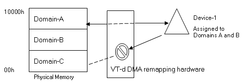
In the above figure, Device-1 is not assigned to Domain-C, so when Device-1 tries to access Domain-C memory location range, it is restricted by the VT-d hardware.
I/O performance through direct Assignment
Software based I/O virtualization methods use emulation of the I/O devices. With this emulation layer the VMM provides a consistent view of a hardware device to the VMs and the device can be shared amongst many VMs. However it could also slow down the I/O performance of high I/O performance devices. VT-d can address loss of native performance or of native capability of a virtualized I/O device by directly assigning the device to a VM.
In this model, the VMM restricts itself to a controlling function for enabling direct assignment of devices to its partitions. Rather than invoking the VMM for all (or most) I/O requests from a partition, the VMM is invoked only when guest software accesses protected resources (such as I/O configuration accesses, interrupt management, etc.) that impact system functionality and isolation.
To support direct VM assignment of I/O devices, a VMM must enforce isolation of DMA requests. I/O devices can be assigned to domains, and the DMA remapping hardware can be used to restrict DMA from an I/O device to the physical memory presently owned by its domain.
When a VM or a Guest is launched over the VMM, the address space that the Guest OS is provided as its physical address range, known as Guest Physical Address (GPA), may not be the same as the real Host Physical Address (HPA). DMA capable devices need HPA to transfer the data to and from physical memory locations. However, in a direct assignment model, the guest OS device driver is in control of the device and is providing GPA instead of HPA required by the DMA capable device. DMA remapping hardware can be used to do the appropriate conversion. Since the GPA is provided by the VMM it knows the conversion from the GPA to the HPA. The VMM programs the DMA remapping hardware with the GPA to HPA conversion information so the DMA remapping hardware can perform the necessary translation. Using the remapping, the data can now be transferred directly to the appropriate buffer of the guests rather than going through an intermediate software emulation layer.
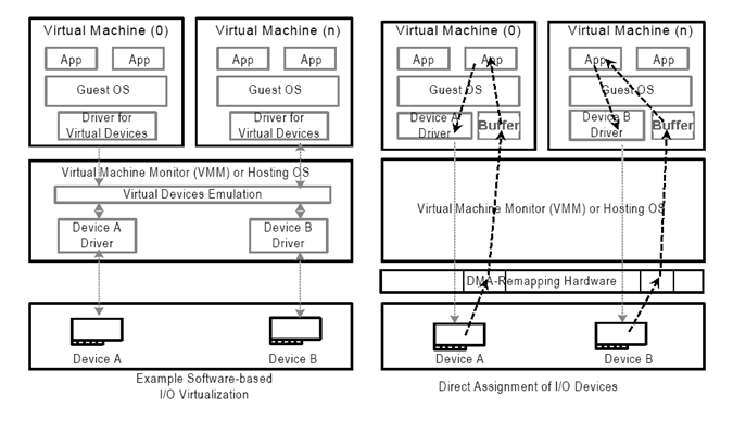
Above figure illustrates software emulation based I/O in comparison to hardware direct assignment based I/O. In the emulation based I/O the intermediate software layer controls all the I/O between the VMs and the device. The data gets transferred through the emulation layer to the device and from the device to the to the emulation layer.
In the direct assignment model, the unmodified guest OS driver controls the device it is assigned. On the receive path the DMA-remapping hardware converts the GPA provided by the guest OS driver to the correct HPA, such that the data is transferred directly to the buffers of the guest OS (instead of passing through the emulation layer). Interrupt remapping support in VT-d architecture allows interrupt control to also be directly assigned to the VM, further reducing the VMM overheads.
Extended Page Tables (EPT)
EPT takes care of memory overheads and provides virtual machines to perform much faster than software or VMM translated memory access. Let’s understand three modes of memory addressing.
- How a normal process access memory on a physical machine.
- How software assisted memory management in Virtual machines with EPT support.
- How memory management is done when EPT is enabled.
Memory Management in Native Machines
In a native system the task of managing logical memory to Physical memory is handled by Operating System. This is accomplished by storing the entries in page table structures. When a process access the logical address of the memory where it thinks the data is stored, the hardware goes through the page table structure to find out the physical address location of the stored data. Frequently accessed logical page number (LPN) to physical page numbers (PPN) of memory address locations are cached by the hardware system in Translation Lookaside Buffer (TLB). TLB is a small cache on the processor which accelerates the memory Management process by providing faster LPN to PPN mappings of frequently accessed memory locations.
Memory Management using VMM
Virtual Machines are run on a hypervisor. In this case, the guest operating systems does not have access to the hardware page tables similar to the natively running operating systems. The VMM emulates the page tables for the guest operating systems and gives the guest operating systems an illusion that they are accessing actual physical pages. The VMM actually runs a page table of its own called Shadow Page tables which is visible to the system hardware. Whenever the guest OS makes a request for virtual address translation to physical memory address, the request is trapped by the VMM, which in turn run through its shadow page tables and provides the address of physical memory location.
While the VMM handles the LPN to PPN mapping quite efficiently, there are times when the page fault occurs considerably slowing down the application and the operating systems. The major penalty comes when the guest OS adjusts its logical mapping. This triggers the VMM to adjust its shadow pages to keep in sync with the logical mappings of the Guest OS. For any memory intensive application running inside the guest OS , this process of syncing pages causes a hefty drop in performance due to virtualization overhead.
Memory Management using EPT
The extended page-table mechanism (EPT) is a feature that can be used to support the virtualization of physical memory. When EPT is in use, certain addresses that would normally be treated as physical addresses (and used to access memory) are instead treated as guest-physical addresses. Guest-physical addresses are translated by traversing a set of EPT paging structures to produce physical addresses that are used to access memory.
EPT translation is exactly like regular paging translation but with some minor differences. In paging, the processor translates Virtual Address to Physical Address while in EPT translation you want to translate a Guest Virtual Address to Host Physical Address.
In regular paging, the 3rd control register (CR3) is the base address of root paging directory. In EPT, guest is not aware of EPT Translation so it has CR3 too but this CR3 is used to convert Guest Virtual Address to Guest Physical Address. Whenever you find your target Host Physical Address, it’s EPT mechanism that treats your Guest Physical Address like a virtual address and the EPTP is the CR3.
So target physical address should be divided into 4 part, the first 9 bits points to EPT PML4E (note that PML4 base address is in EPTP), the second 9 bits point the EPT PDPT Entry (the base address of PDPT comes from EPT PML4E), the third 9 bits point to EPT PD Entry (the base address of PD comes from EPT PDPTE) and the last 9 bit of the guest physical address point to an entry in EPT PT table (the base address of PT comes form EPT PDE) and now the EPT PT Entry points to the host physical address of the corresponding page.
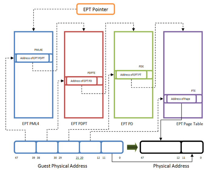
In this way, a simple gust Virtual to host Physical Address translation involves accessing 4 physical address. The processor internally translates all tables physical address one by one, that’s why paging and accessing memory in a guest software is slower than regular address translation.
IOMMU
Another take on IOMMU/EPT is here
I/O Virtualization
Virtual Machine Device Queues (VMDq)
Intel’s VMDq is a technology that eases the problem of the VMM handling all the network I/O for every VM on the host. VMDq is more efficient and provides better network I/O scaleability than that of the VMM’s emulation of hardware functions.
VMDq is implemented in the hardware of an Intel Network Interface Card (NIC) and offloads some of the management of the I/O processing from the VMM. It does this by doing the layer 2 classification/sorter functions in the NIC hardware vs. doing at the VMM layer. Also, VMDq has a separate queue for each (VM) with each queue having its own cpu hardware interrupt. This in-turn enables multiple VMs to handle network I/O at the same time. Here’s a YouTube video that explains VMDq in a very nice automated way.
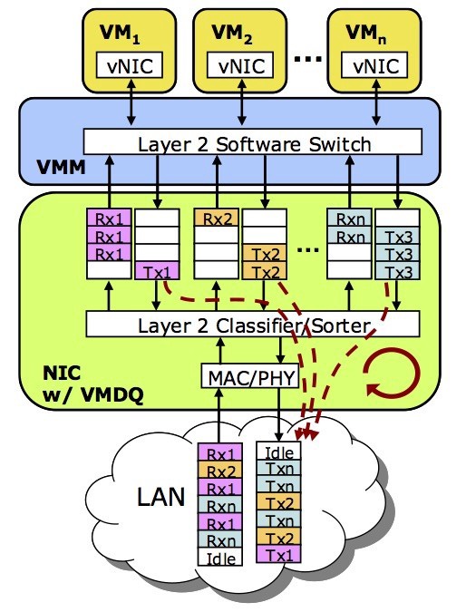
Even with VMDq, there is still room for performance improvement as the VMM still has to handoff the I/O (packet) to the VM.
Single-Root I/O Virtualization (SR-IOV)
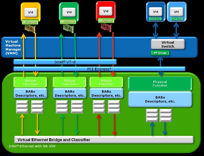
Single Root I/O Virtualization (SR-IOV) is an extension to the PCI Express (PCIe) specification. SR-IOV being a specification provides a standard for I/O Virtualization of hardware with the goal for greater interoperability. SR-IOV implementations provides a single physical PCIe device to appear as multiple physical devices.
SR-IOV offers even better performance than that of VMDq. The VM has direct access to the Intel SR-IOV NIC and has it’s own dedicated hardware resources for processing network I/O (packets). Unlike VMDq, SR-IOV eliminates the VMM from processing any of the network I/O (packets). SR-IOV copies the network packet to/from the associated NIC Virtual Function directly to/from the VM’s virtual memory address via Direct Memory Access (DMA). Intel VT-d (direct memory remapping) and Intel’s chipset make the VM DMA possible as VM’s don’t have direct access to physical memory. VMs only have virtual memory access. Here is another YouTube video that explains SR-IOV in a very nice automated way.
